


Empire Industries
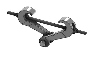
Fig. 218 Malleable Iron Center Load Beam Clamp

- SKU:
- 218B
- Availability:
- Usually Ships Same Day
- Weight:
- 2.46 LBS


Description

Fig. 218 Malleable Iron Center Load Beam Clamp
Empire Fig. 218 Malleable Iron Center Load Beam Clamp is designed for the suspension of a hanger rod from the center of an I-beam.
The clamp accommodates I-beam flange widths from 2-3/8" through 7", with flange thickness not to exceed .60". It is normally used in conjunction with the Fig. 157 Extension Piece, which provides 1" of vertical adjustment.
Product Highlights
- Designed to suspend a hanger rod from the center of an I-beam
- Accommodates flange widths from 2-3/8" through 7"
- Maximum flange thickness: .60"
- Maximum hanger rod size: 7/8"
- Normally used with the Fig. 157 Extension Piece
- Fig. 157 provides 1" of vertical adjustment
- Available in plain malleable iron and electro-galvanized finishes
- Maximum recommended load for the clamp: 1,365 lbs.
Center Load Beam Support
The Fig. 218 is designed to provide a hanger rod suspension point from the center of an I-beam. The clamp accommodates beam flange widths ranging from 2-3/8" through 7".
Flange thickness must not exceed .60".
Technical Specifications
| Manufacturer | Empire Industries |
|---|---|
| Figure | 218 |
| Product Type | Center Load Beam Clamp |
| Material | Malleable Iron |
| Available Finishes | Plain Malleable Iron (218B) or Electro-Galvanized (218G) |
| Service | Suspension of a Hanger Rod from the Center of an I-Beam |
| I-Beam Flange Width | 2-3/8" to 7" |
| Maximum Flange Thickness | .60" |
| Maximum Rod Size | 7/8" |
| Bolt Diameter | 7/16" |
| Weight | 2.49 lbs. each |
| Maximum Recommended Load | 1,365 lbs. |
| Related Component | Fig. 157 Extension Piece |
Fig. 157 Extension Piece
The Fig. 218 is normally used in conjunction with the Empire Fig. 157 Extension Piece. The Fig. 157 provides 1" of vertical rod adjustment.
View the Fig. 157 Extension Piece
Standards & Approvals
When used with the Fig. 157 Extension Piece, the assembly complies with:
- Federal Specification WW-H-171-E, Type 30
- Federal Specification A-A-1192A, Type 30
- MSS SP-58, Type 30
- MSS SP-69, Type 30
Assembly & Ordering Information
Specify the figure number and finish when ordering the Fig. 218. The Fig. 157 Extension Piece shown with the clamp is not included.
The manufacturer submittal notes Fig. 229 for the complete assembly with extension piece.
Important Ordering Notes
Specify the figure number and finish when ordering. Confirm the I-beam flange width and thickness before selection. The flange thickness must not exceed .60". The Fig. 157 Extension Piece is not included with the Fig. 218 clamp. For a complete assembly with extension piece, the manufacturer submittal references Fig. 229.
Product Documents
Product Questions
What is the Fig. 218 Center Load Beam Clamp designed for?
It is designed for the suspension of a hanger rod from the center of an I-beam.
What I-beam flange widths will the Fig. 218 accommodate?
The clamp accommodates flange widths from 2-3/8" through 7". The flange thickness must not exceed .60".
What is the maximum hanger rod size?
The manufacturer submittal lists a maximum rod size of 7/8".
Is the Fig. 157 Extension Piece included?
No. The Fig. 157 Extension Piece shown with the clamp is not included. The Fig. 218 is normally used with the Fig. 157, which provides 1" of vertical adjustment.
What finishes are available?
The manufacturer lists plain malleable iron as Fig. 218B and electro-galvanized as Fig. 218G.
What is the maximum recommended load?
The Fig. 218 clamp has a manufacturer-listed maximum recommended load of 1,365 lbs.

Ask Willy: Product Information & Help
Contact the GetPipe.com team for help with Fig. 218 Malleable Iron Center Load Beam Clamp.


